Drawing More Complicated Shapes
Drawing More Complicated Shapes
Several specialized drawing tools let you quickly create complex shapes in Canvas X Draw. Drawing grids, stars, polygons, concentric circles, cubes, and spirals is as easy as drawing rectangles. The following tools create specialized vector objects.
| Concentric Circles: Nested circles or ovals |
| Cube: Square and rectangular boxes in isometric views |
| Gridmaker: Rows and columns of boxes |
| Multigon: Stars and complex polygons |
| Spiral: Lines in spiral patterns |
| Registration Marks: Registration marks around a graphic for which you intend to print separations |
| EasyShapes: All kinds of shapes, including arrows, flow chart boxes, dialog balloons, symbols, and banners |
| Calendar: Calendars |
| QR Code: QR codes |
| Smart Lines: Connect objects with smart lines. |

In most cases, you can treat these vector objects like all others. You can move them and resize their bounding boxes. They can be rotated, flipped, and scaled. You can apply strokes, pen inks and fill inks to them. However, most of these objects are compound objects, which means that they are made up of separate objects. Therefore, some inks and other effects appear differently when applied to these objects than to simple vector objects like rectangles and ovals.
Some of the specialized objects have unique editing features. For example, you can twirl the points of a star, star outline, or framed star by dragging special handles. You can also specify the number of points of a star, the number of rows and columns in a grid, the number of rings in concentric circles, and the number of revolutions in a spiral. You can draw a cube with or without a perspective effect. Methods for drawing and modifying all of the specialized objects appear with the individual tool descriptions that follow.
You can also convert most specialized vector objects to paths, which lets you edit the object anchor points and segments. (See Converting Objects and Text to Paths.)
Drawing Concentric Circles
The Concentric Circles tool draws nested rings of ovals or circles. You can set the number and spacing of the rings before or after you draw concentric circles.
To Use the Concentric Circles Tool:
- Select the Concentric Circles tool.

- Drag to draw a bounding box that defines the size of the concentric circles object. A rectangular bounding box creates concentric ovals; a square bounding box creates true circles.
- When you finish, the concentric circles object is selected.
To Draw True Concentric Circles:
Press Shift to constrain the bounding box to a square when you drag the Concentric Circles tool.
To Draw from the Center:
- Press Ctrl to draw from the center outward with the Concentric Circles tool.
- Press Shift also to draw perfect circles outward from the center.
To Edit a Concentric Circles Object:
- Select the Concentric Circles object.
- In the Properties bar, adjust the settings, such as the number of rings and the spacing.
- Press Enter to apply the settings to the object.
To Configure the Concentric Circles Tool Before You Draw an Object:
- Before you draw an object, select the Concentric Circles tool.
- In the Properties bar, adjust the settings to configure the Concentric Circles tool.

Drawing Cubes
To Draw a Cube:
- Select the Cube tool.

- Drag to draw the rectangular back face of the cube.
- Release the mouse button when the back face of the cube is set as you want. An unanchored cube then follows the cursor.
- Position the front face of the cube so it appears at the length and angle you want, and then click to anchor it.
To constrain the faces of the cube to perfect squares, hold down the Shift key while drawing the back face.
To Give the Cube a Perspective Effect by Enlarging the Front Face:
Hold down the Alt key before you anchor the cube.
To Edit Cubes:
Do one or more of the following:
- To change the height or width of a cube, click the cube to select it, and then drag a corner handle.
To reshape a cube by moving a side, double-click the cube to place it in Edit mode. A black circular handle appears on each of the six faces of the cube.
When you point to a handle, the outline flashes on the corresponding side of the cube. You can drag the handle to move that side. Click outside the cube to leave Edit mode.\
You can identify whether you are in Cube Edit mode by the Status bar or the following icon in the Properties bar:

Drawing Spirals
The Spiral tool draws a smooth, spiraling curve. You can set the number of spiral turns before or after you draw a Spiral object.
To Use the Spiral Tool:
- Select the Spiral tool.

- Drag diagonally to specify the size of the spiral curve.
To Create a Circular Spiral:
Press Shift and drag.
To Configure the Spiral Tool:
- Select the Spiral tool.
- In the Properties bar, set the number of spirals and the spiral direction.
To Change the Number of Spirals in an Object:
- Select the Spiral object.
- In the Properties bar, change the number of spirals and press Enter.
Drawing Grids
The Gridmaker tool draws grids of rows and columns. Set the number of rows and columns before or after you draw a grid object.
To Use the Gridmaker Tool:
- Select the Gridmaker tool.

- Drag diagonally to define the grid’s bounding box.
To Create a Square Grid:
Press Shift and drag.
To Configure the Gridmaker Tool:
- Select the Gridmaker tool.
- In the Properties bar, set the number of boxes comprising the grid as well as the cell size.
If you set Boxes Across to 0, the grid has no vertical lines. If you set Boxes Down to 0, the grid has no horizontal lines.
To Modify Grid Object:
- Select the Grid object.
- In the Properties bar, change the number of boxes or cell size and press Enter.
To Separate a Grid into Lines:
Adjust the individual lines that comprise a grid by converting it to a path and then ungrouping it.
- Select the Grid object.
- Choose Path | Convert to Paths.
- Choose Object | Ungroup. The grid object separates into individual lines.
Drawing Multigon Shapes
Use the Multigon tool to draw all types of multi-sided objects, including triangles, hexagons, pentagons, octagons, stars, circular starbursts, and similar shapes. To set the number of sides and the style of a multigon, configure the Multigon tool before you draw.
To Draw with the Multigon Tool:
- Select the Multigon tool.

- Drag diagonally to define the multigon’s bounding box.
To Make the Bounding Box Square:
Press Shift and drag.
To Configure the Multigon Tool:
- Select the Multigon tool.
- In the Properties bar, set the multigon options.
- Press Enter.
Multigon Options
The available options depend on the selected multigon style.

Style | Select the style of the multigon:
|
Points | For stars, framed stars, and star outlines, enter the number of star points from 3 to 100. For other styles, enter the number of sides from 3 to 100. |
Smooth | Turn this option on to smooth the object’s angles. |
Inset Ratio | Drag the slider to change the interior area of stars, framed stars, and star outlines. |
Pinwheel angle | For stars, enter a value of more or less than 0 degrees to bend the points. Negative values bend the points counterclockwise. |
Presets | Choose a preset style in the pop-up menu. |
To Save Multigon Presets:
- Select the Multigon shape you want to save as a preset.
- In the Properties bar, click the Presets menu, and select Save shape.
- In the Save Shape dialog box, enter a name for the shape, then click OK.
To Delete Multigon Presets:
- Select the Multigon tool.
- In the Properties bar, click the Presets menu, and select Delete shape.
- In the Delete Shape dialog box, select the preset you want to delete, then click OK.
When you save and delete styles, they remain saved or deleted whether you click OK or Cancel to close the Multigon dialog box.
To Edit Star Multigon Objects:
You can edit Star Multigons (framed star, star, and star outline styles) to adjust the twirl and radius of the object’s points. The following procedures do not apply to frames, spokes, or wheels.
Double-click the Star Multigon object to put it in Edit mode.
An outer handle and inner handle appear on one point of the star.
You can identify whether you are in Multigon Edit mode by the Status bar or the following icon in the Properties bar:

- Do one or more of the following:
- To change the length of the star points: Drag the outer handle inward or outward from the center of the star.
- To twirl the points: Drag the handle clockwise or counterclockwise.
- To change the position of the inner points: Drag the inner handle inward or outward from the center.
- Press Esc or double-click outside the object to exit Edit mode.
Drawing Registration Marks Manually
Use the Registration Mark tool to manually draw registration marks around a graphic for which you intend to print separations. Use the Registration Mark tool when:
- The size of the graphic occupies the printable area, therefore preventing the print separation marks from appearing.
- You layout different graphics on a single sheet and plan to print each graphic individually.
To Draw Registration Marks:
- Select the Registration Mark tool.

In the Properties bar, set the location, default size, and fill color of the registration mark, then click the Create button.
This draws the first registration mark, and sets the defaults for registration marks in the current Canvas X Draw session.
- Select the Registration Mark tool again, then click in your document to draw additional registration marks.
If you want to place a registration mark in a precise location, you can select the registration mark in your document, and set the X/Y coordinates in the Properties bar.
Drawing Crop Marks
For print production, you can draw crop marks around specific objects in your document. This is useful when you want to control the exact placement of crop marks, or you want to output several illustrations with crop marks around each illustration on one page.
Crop marks are short vertical and horizontal lines that indicate the border where an illustration or page can be trimmed.
When you use the Crop Marks commands, Canvas X Draw draws the crop marks as vector lines on the current layer in the document. Each crop mark consists of two lines. You can select the lines and perform operations on them as you would other vector objects.
To Place Crop Marks:
- Select the objects you want to place crop marks around. You can select one or more objects of any type.
- Choose Object | Options | Crop Marks.
- In the Crop Marks dialog box, in the Outset box, enter the distance you want the crop boundary to be from the selection.
- If one object is selected, the selection boundary is the object’s bounding box.
- If more than one object is selected, the selection boundary is the smallest rectangle that would enclose all the selected objects.
Select the Use Registration Ink option to assign Registration ink color to the crop marks.
Registration ink appears black, but it prints on all plates when you output color separations. This option should be selected if you want the crop marks to print on all plates.
- Click OK to create the crop marks.
Drawing Calendars
To Use the Calendar Tool:
- Define at least a 1-inch x 1-inch rectangle.

- Select the Calendar tool and the cursor changes to a crosshair.
- Drag the crosshair to form at least a 1-inch x 1-inch rectangle and the Calendar dialog box opens so you can define your calendar.
To Create a Calendar:
- Enter the starting month and year. The default month is the current month and year.
- Enter the ending month and year. The default month is the current month and year.
- Enter the number of columns; e.g., if your calendar is for 8 months and you enter 4 in this field, your calendar would have 4 columns and 2 rows.
Select the Include Lunar Phases checkbox if you want lunar phases to appear on your calendar.
Drawing QR Codes
You can create and place QR codes that can be read by certain applications for smart phones.
To Create a QR Code:
- Select the QR Code tool in the Toolbox.

- In the Properties bar, enter a string, such as an URL for a web site, in the QR String field.
- In the Properties bar, select an option from the Color drop-down menu.
- Do one of the following:
- Set the X and Y coordinates, width and height, and then click Create.
- Click and drag in the current document to define the dimensions of the QR code. You can drag while pressing the Shift key to retain the width and height.
To Edit a QR Code's String:
- Select the QR Code object.
- In the Properties bar, type a new QR string.
- Press the Update button.
To Edit the Color of a QR Code:
- Select the QR Code object.
- In the Properties bar, select another color from the Color drop-down menu.
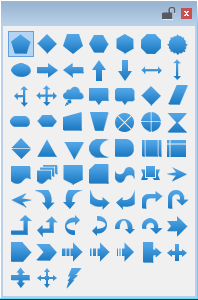
Drawing EasyShapes
You can use EasyShapes to quickly add all kinds of shapes, including arrows, flowchart symbols, dialog balloons, symbols, and banners.
To Use the EasyShapes Tool:
- Select the EasyShapes tool.

- Select an EasyShapes tool from the palette. The cursor switches to a crosshair in the drawing area.
- Drag the cursor in the drawing area. The new object appears with the current fill ink, pen ink, and stroke properties, and is selected.
If the EasyShapes tool you used is one that creates a preset text object, an insertion point appears inside the shape. Type the text. When you finish, press Esc to end Text Edit mode.
If the EasyShapes tool you used does not create a preset text object, Canvas X Draw will create a text object if you begin typing. When you finish typing, press Esc.
- When you have finished using EasyShapes, press Esc.
You can also create an EasyShapes by entering values in the X/Y and width/height fields in the Properties bar and then clicking the Create button. By default, the X/Y coordinates are set at 0,0.
When drawing pentagons, diamonds, hexagons, octagons, and triangles, you can enable the Equilateral checkbox in the Properties bar to ensure all sides are equal. Next to the Equilateral checkbox, you can enter a value in the Side Length field to specify your desired side lengths.
To Change All Alike EasyShapes:
- Select the EasyShape.
- In the Properties bar, press the Select Same Shape button.
- All matching EasyShapes are now selected. Select a new shape from the Shape drop-down menu. All selected shapes are changed.
Connecting Objects with Smart Lines
Use Smart Lines to link one or more objects to a single object. Draw multiple Smart Lines between objects and link Smart Lines to other Smart Lines. Smart Lines change length and angle to maintain connection to the linked objects. Or use the Polygon and Smooth Polygon Smart Line tools to draw connecting polygon lines between objects.
| |
| |
| |
| |
| Polygon |
| Smooth Polygon |
|


To Use a Smart Line Tool:
- Select a Smart Line tool.
- Drag from one object to another object. When you release the mouse button, Canvas X Draw creates the Smart Line.
To Change Smart Line Type:
- Select the Smart Line with the Selection tool. The Type menu appears in the Properties bar.
- Choose another Smart Line type from the menu. The line changes immediately.
You can quickly select and edit the attributes of smart lines without clicking each one individually. Select the type of Smart Line tool you want to edit from the Toolbox and press Ctrl + A.
To Change the Position of Start and End Points:
Select the Smart Line with the Selection tool. The Properties bar displays the X/Y values coordinates for the start and end points.

- Enter new values in these fields in the Properties bar and press Enter. The Smart Line shifts accordingly.
- Start Direction: For Kinked Smart Lines, select either Auto, Horizontal, or Vertical to change the slope of the Start direction. For Dogleg connections, select either Auto, Left Always, or Right Always to change the direction of the dogleg portion.
- End Direction: Select either Auto, Horizontal, or Vertical to change the slope of the End direction.
- Tab Length: This value refers to the horizontal portion of a dogleg connection created with the Dogleg Connector tool. Enter a value in this field and press Enter. The angled portion of the connection does not change.
If the Dogleg Connector or a Kinked or Smooth Kinked Smart Line is selected, the Properties bar contains additional information, which is not applicable to Basic Smart Lines.
To Unsmooth a Smooth Kinked Smart Line:
Select the line and choose Kinked from the Type menu in the Properties bar.
To Smooth a Kinked Smart Line:
Select the Kinked Smart Line and choose Smooth Kinked from the Type menu.
To Use the Connection Point Tool:
This tool is used to move the anchor points of a vector object. You can also add and remove anchor points.
- Select the Connection Point tool. The cursor changes to a crosshair.
- Click on an existing vector object. The anchor points appear. When you place the crosshair on an anchor point, the anchor point is emphasized.
- Click the crosshair on an anchor point and drag it to its new location. You cannot move an anchor point beyond an object’s bounding box.
- To add an anchor point: Ctrl-click the crosshair anywhere within the vector object.
- To remove an anchor point: Press Ctrl+Shift and click the crosshair on the existing anchor point that you want to delete.
To Use the Polygon or Smooth Polygon Smart Line Tool:
These tools are used to draw polygon lines between objects.
- Select the Polygon or Smooth Polygon Smart Line tool. The cursor changes to a crosshair.
- Click on an existing vector object. The anchor points appear.
- Click the crosshair on an anchor point.
- Click on a second object and click the crosshair on an anchor point.
Press Esc to exit Edit mode.
If you move one of the objects, the connecting polygon line retains the connections between the objects.
Related Articles
Drawing More Complicated Shapes
Drawing More Complicated Shapes Several specialized drawing tools let you quickly create complex shapes in Canvas X Draw. Drawing grids, stars, polygons, concentric circles, cubes, and spirals is as easy as drawing rectangles. The following tools ...Drawing More Complicated Shapes
Drawing More Complicated Shapes Several specialized drawing tools let you quickly create complex shapes in Canvas X Draw. Drawing grids, stars, polygons, concentric circles, cubes, and spirals is as easy as drawing rectangles. The following tools ...Drawing by Numbers
Drawing by Numbers Several drawing tools give you the option of entering dimensions to draw objects precisely. This method can be easier than dragging the mouse and watching data in the Properties bar to draw objects to precise dimensions. You can ...Drawing by Numbers
Drawing by Numbers Several drawing tools give you the option of entering dimensions to draw objects precisely. This method can be easier than dragging the mouse and watching data in the Properties bar to draw objects to precise dimensions. You can ...Drawing by Numbers
Drawing by Numbers Several drawing tools give you the option of entering dimensions to draw objects precisely. This method can be easier than dragging the mouse and watching data in the Properties bar to draw objects to precise dimensions. You can ...